|
Arduino Based Home ControllerI've mucked around with a few micro-controller chips in the past - including the Motorola 68HC705K1, PIC (16F84) chips, and PICAXE. About a year ago my son bought me a Arduino card, and I've only recently started to play with it. The card is actually a Seeeduino (Arduino clone) with the 16K of memory. I decided to build a home controller with hardwired inputs and outputs and wireless control of mains power switches. I also wanted the system to have it's own web page for control by any PC on my home network. (The link to the program I've written is at the bottom of this page). The block diagram is as follows: 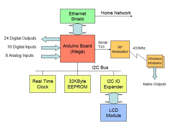 As can be seen, the home controller uses an Arduino Mega - needed because the program is getting large and because I wanted a reasonable number of IO. An I2C bus connects a Real Time Clock, 32K EEPROM (which stored fixed HTML text, time rules and other fixed data such as sunrise and sunset times), and an LCD connected via an I2C IO module. The system executes time based rules which enable outputs to be turned on or off at certain times of the day. The system understands "sunrise" and "sunset" and offsets, so rules can be set up to turn on lights 15 minutes after sunset. PC <-> Arduino ProtocolThe controller generates it's own simple web page - showing digital outputs (status and auto/manual state), digital inputs, analog inputs and state of major internal variables. The page auto refreshes every 15 seconds. 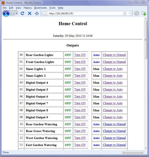 The general protocol is based on HTML - meaning that external systems can enquire of status information and control outputs using simple HTML commands. For instance, sending "http://192.168.xx.xx/HIOST01" will turn on output 1 and return a full web page, and sending "http://192.168.xx.xx/HIOISA" will activate the security system. So it's pretty easy to create web pages with links that call the commands (e.g. <a href=HIOST01>Turn ON</a>). Note that "HIO" is a marker that the arduino client handling code uses to look for a command string. The code below is used to get the command code and call additional subroutines to read and process additional characters and execute the commands. char getInputCommand(Client client) {An external server can also execute command by sending standard http requests. I use "curl" on my linux server to grab data and execute periodic commands (there is cURL for Windows but I haven't tried it - should work though). For instance "http://192.168.xx.xx/HIOd" will send a minimally formatted data string of input and output statuses to the server for it to process as a regular text file. Some details of the protocol are: Format of PC<->Arduino HTTP protocol Construction PicturesHere's some pictures of the assembled system so far. It's built into a 2RU 19" rack case. The Arduino Mega and ethernet shield (connected using the Arduino Mega Ethernet Shield Hack, and mounted so the ethernet port and USB port stick out the side of the case. The digital inputs are protected by 4.7V zener diodes and resistor/capacitor filters. They should be able to take up to 15V ok and withstand any noise and short term surges. The digital outputs use ULN2803 darlington drivers chips for 24 outputs (00-23). Outputs 24 to 31 are virtualised as to the remote wireless system. Analog inputs have a bit of filtering to reduce noise. 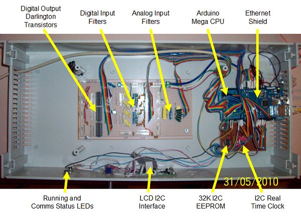 The LCD is a 4 line parallel interface (LCM2004A) and an I2C chip PCF8575 16 I/O expander provides an 8 bit parallel interface and write pulse functions. 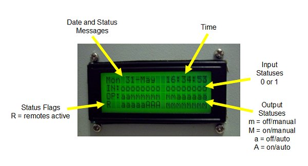 The LCD display is updated every 500ms. Input and output statuses are displayed along with a variety of other date rotated through line 1. Note that outputs have auto or manual mode. In auto, time and logic rules apply. In manual, time and logic rules do not apply and the output must be turned on or off from the web page. 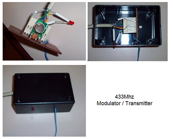 The 433Mhz wireless transmitter is in a separate box connected by 3 wires (+5V, Gnd, data). This will enable is to be positioned for best radio coverage. Program After a few requests, the entire current version of the program I've written is downloadable from the link below as a zip file. Simply unzip and put the directory in your Arduino_Projects directory and you should be able to open it. Note the major functions are on separate pages. Of course use and abuse at your own risk. I'm a hacker - not a programmer, so expect some really badly written stuff. Donwload -> Home_Control_0v15.zip
|
|
Created by Greg Smith -
Hosted on vps2.smithonline.id.au (Amazon Lightsail) on Centos -
Server by Apache -
CMS by CMSimple.dk -
Template by
Websitetemplate.org
![]()